Wednesday, 29 August 2018

Tunnel Top Panels

Another easy job completed.  The top tunnel panels require holes drilling for the M6 dome heads and of course the hole for the gearstick needs to be carefully measured and then cut:


Everything fits nicely together.  Next job was to remove the protective plastic and give them a quick clean:


Same process as before applied, carpet glue and some patience:


Finished result, nothing is attached its all just resting in place until I complete the wiring, pilot holes and carpets:


Clocks will be here tomorrow so I suspect I will be wiring them in this weekend.

Tuesday, 28 August 2018

Aux Console

Nice and therapeutic one to do whilst waiting for the ECU and Clocks, gives me time to rest my back as well as 90% of this was done indoors.

I purchased the lower dash panel from GBS, its made out of aluminium and it saves me having to fabricate something myself.  First job was to mark up the centre line and where I wanted each button to go:


A quick test of my hole driller on some scrap confirmed the fit and finish:


Onto the real thing....gulp.....and fhew, all fine without any drama:


Using the same leatherette I used for the dashboard I used some carpet glue and stuck it on - after much faffing about I am really pleased with the finish:


Out comes the scalpel:


And the final product:


Chuffed with that!  Hopefully that is the fiddliest part of the tunnel cover, I need to remember to cut out the leather for the pre-drilled holes ready for the dome head bolts.   

Monday, 27 August 2018

Exhaust Silencer, Lambda and bits & bobs

Lots done this bank holiday - getting closer to first start, the ECU and Clocks are on order and hopefully arrive before the weekend.

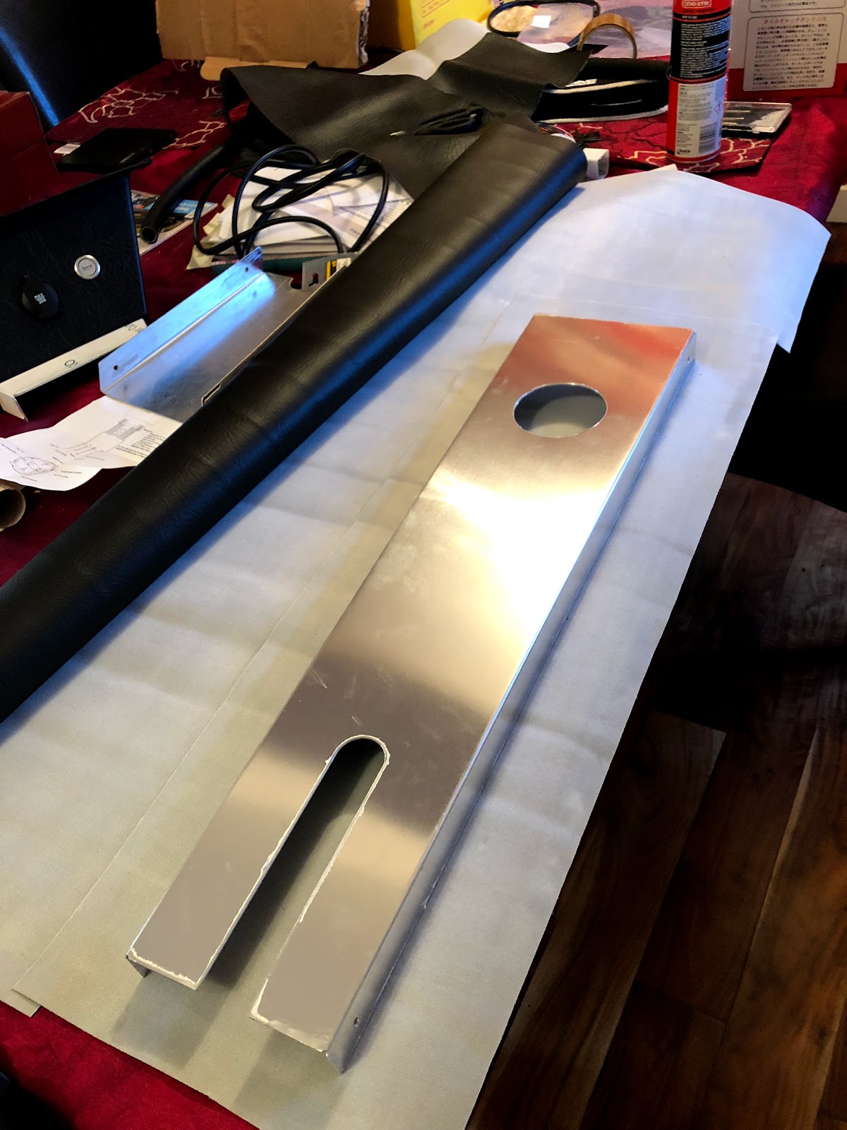
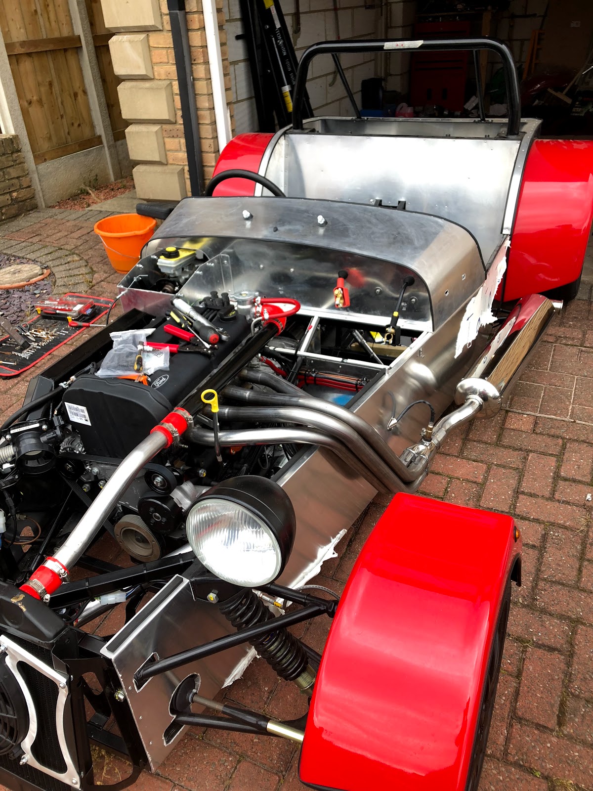
First job of the day was to set my stall up, took the car out of the garage as I knew the manifold would require some careful measuring and cutting:


Next job was to mark where the manifold needs to be cut based on the rear mount, I had some scrap aluminium in the garage which I used against the side of the car just in case:


Excess removed with my dremmel and the extension, great piece of kit.  Next was onto the rear exhaust mount which needs to be drilled from underneath.  I was planning on making up a template and then drilling through from the top, however as I only get one shot at it I put the rear on axle stands:


Then went for a pilot hole using my right angle adaptor

The manifold needs a bit of lube as its a tight fit, it must be done before final fitment of the rear bracket.  Nice and neat:


Looking good:


Next onto the lambda sensor.  I read on a couple of blogs that this needs to be kept connected to the sensor at all times due to the sensitivity of the device; I haven't confirmed this although chose to go with it.  First task was to mark a pilot hole in the side:


The lamda sensor is the same size as a washer so I used that as template, masked it up and then opened up the hole with a mix of drill bits and eventually the dremel, nice and neat:


The three rivet holes allowed me to attach a clam shell which finishes off the hole nicely:


Looking good:


There were a handful of other jobs completed this weekend that dont really warrant pictures, one of which was the driveshaft - this must be split into two as it simply doesn't fit into the tunnel without. 

I didn't have to remove either the gearbox or the diff to get it in and that's another thing ticked off.

I think I'll do some work on the centre console and aux switches as these can be done indoors before my ECU and Clocks arrive.   Getting excited now :)

Sunday, 19 August 2018

IACV Mounting, Quick Shift and Exhaust Manifold

Lots of work completed that doesn't really photo well - the engine loom is fitted and well, you cant see it! (which is the general idea).

I spoke to GBS about mounting the IACV and they didn't say there was a specific place for it and recommended somewhere near the swirl pot.  No room there so I posed on Rhocar to check my thoughts on mounting towards the front of the car near the radiator.  I was concerned at the distance increase, no real consensus.   I found on another builders blog they had mounted the IACV on the same bracket the coil pack sits on - that is what I went with and am really pleased with the result:


It looks almost stock!  Great, filter required on the underside on one of the inlets and a vaccum pipe required other side going to the plenum - the end result should be nice and neat as well as functional.

Next up was the Exhaust Manifold - the manifold purchased from GBS must have a slightly thinner flange on it as the bolts don't nip up tight, they are about 2mm too long and as a result there is no way the manifold will seal.   I did a fair amount of research on what type of bolts to use (with a couple of reference to GBS supplied ones) I came to the conclusion shortening the stock bolts was the way forward.

Using my vernier, dremmel and some patience all 6 bolts were cut to length and the manifold is now on:


Next up was the MT75 quick shift from Kitspares, the instructions are clear and it was easy to fit.  I had to take off the existing "spider??" which was attached via circlip and pin, the left hand is the GBS replacement:


One thing I found easier was to keep the pin to temporarily connect the quick shift up to get the required 90 degree angle when in neutral.

GBS instructions say to finger tight everything up and then adjust the angle but the problem is to adjust the angle you have to take the bracket off.  To find what the angle will be the selector needs to be connected to the gearbox, hence using the pin to temporarily connect.

Not too much of a faff and it feels really solid and well engineered:


I need to return the exhaust silencer I purchased from kitspares and swap it for one including CAT (I ordered the wrong one).   I don't think I am too far off starting the engine but some big purchases are in order (clocks + ECU).


Sunday, 5 August 2018

Engine Loom - Part 2

Well, I hope it works :)  I've spent so long on this loom but loved every minute of it.  I didn't do it to save time or money, I did it to learn and I've definitely done that!

There aren't many pictures to this one as they don't really do it justice - in the flesh it looks good and I am confident all the pin outs are correct.  I've tested every single one of them (several times!) and its now fitted to the car.   The thing is its completely hidden away now, which is great and I have achieved what I wanted, the bad thing is no one will ever know the effort that went into it!


Some notes:


  • Those of you with a keen eye will notice the Spartan2 wide band lamda controller on the left.  After researching wide band, narrow band, closed and open loop systems I went with this (https://www.14point7.com/products/spartan-lambda-controller-2).  Its a no brainer really, it make sense to go wide band and this is the best value\rated kit available.
  • I'll cut the earth wire down to length and terminate it when the ECU is fitted, the earth point is already in place so required length is unknown.
  • I'm waiting on a connector for the oil pressure switch, it was difficult to find but managed to find one available on eBay, should be here next week.
  • The other connector I need is for the oil pressure clocks - that will come with the clocks when I purchase them.  Still undecided if I should go down the smiths gauge route or go digital (digital is appealing most)
  • Every single connection has been soldered, heat shrunk and tested - I took my time with each of them and made sure they were all 100%.
  • Every pin has been tested for continuity, the wire gauge was defined by emerald in their fly lead.
  • I used a combination of resources to map the various ECU pin outs and GBS engine loom pinouts.  GBS were helpful on their forum when I asked for a pin out list for the engine harness, what I had already researched matched what I was told which is always a good sign
  • The emerald documentation is great with detailed information including examples
  • All of the connectors and sensors are available direct from emerald
  • The Ford wiring diagram I have was very helpful, especially working out sensor pins
Its now in the car, done.   Its been a mission and I am now one step closer to turning they key....

Pinouts are as below - please feel free to use these for reference but of course do *not* take them as gospel, check your own and do your own reasearch!

Emerald K6 Pins

PIN CONNECTION COMMENTS
1 Injector Driver 2 Injector Driver 2, PIN 2  as per manual
2 N/A N/A
3 IACV PWM control output IACV PWM control output, PIN 2
4 Main Relay Driver To ENGINE HARNESS PIN 3, Pink
5 COIL 2 (CYL 2+3) To coil pack PIN 3 (Cylinter 2 +3)
6 Cooling fan relay control To ENGINE HARNESS PIN 4, Orange
7 N/A N/A
8 TPS Input To TPS Input PIN 2 
9 Lambda Supply Lambda Supply - SPARTAN2 (TBC)
10 N/A N/A
11 Ignition sense input 12v supply via ignition switch, to ENGINE HARNESS PIN 1, Red.  Also IACV PIN 1
12 Tacho output signal 0-12v pulsed output, to ENGINE HARNESS PIN 6, Purple
13 N/A N/A
14 N/A N/A
15 Cam Position Sensor Input To Cam Sensor, PIN 1
16 Air temperature signal input Air temperature sensor input
17 N/A N/A
18 N/A N/A
19 Shift-light driver Shift-light output (switched earth), to ENGINE HARNESS PIN 7, Grey
20 Fuel pump relay driver Fuel pump relay driver, to ENGINE HARNESS PIN 5, Green
21 N/A N/A
22 N/A N/A
23 Injector driver 3 Injector Driver 3, PIN 2 as per manual
24 Injector driver 1 Injector Driver 1, PIN 2 as per manual
25 COIL 1 (CYL 1+ 4) To coil pack PIN 1 (Cylinter 2 +3)
26 Injector driver 4 Injector Driver 4, PIN 2 as per manual
27 N/A N/A
28 +12v Ignition supply Supply from main relay or common with pin 11, to ENGINE HARNESS PIN 2, Black. Also to coli pack PIN 2 and ALL INECTORS @ PIN 1
29 ECU earth Good earth (direct to battery), also to HP Fuel Pump.
30 Sensor earth Common earth for air, coolant & throttle sensors.  To Crank Shield, TPS PIN 1, Coolant ECU Sensor, Air ECU Sensor, Lambda Driver SPARTAN
31 Crank, main trigger signal input Crank sensor, PIN 1
32 Main trigger sensor earth Earth return for main/cam trigger sensors. To Crank sensor, PIN 2 and CAM sensor, PIN 2
33 Coolant temp signal input To coolant ECU sensor
34 Lambda Power Lambda input SPARTAN
35 AuxIn35 Removed - however, cable left in loom and terminated.
36 N/A N/A

GBS Engine Loom Pins

PIN # COLOR COMPONENT TO ECU EMERALD PIN
1 RED 12v ignition supply (switch)  YES 11
2 BLACK ECU ignition relay supply YES 28
3 PINK main relay control (coil, Injection, Lambda)  emerald switches this to earth YES 4
4 ORANGE cooling fan relay drive, emerald switches this to earth  YES 6
5 GREEN fuel pump relay driver, emerald switches this to earth YES 20
6 PURPLE tachometer output signal YES 12
7 GREY shift light driver YES 19
8 WHITE oil pressure gauge NO N/A
9 YELLOW oil pressure warning lamp NO N/A
10 PURPLE water temp gauge NO N/A
11 RED alternator warning lamp red horizontal terminal on alternator NO N/A
12 GREY fuel pump + grey supply for high pressure fuel pump NO N/A