Tuesday, 29 January 2019

Windscreen Part 2

Following on from the previous post it was time to start drilling the holes for the windscreen frame.  The factory had advised me to use self tappers cut down to 4mm, I decided a slightly different route.  It is important to keep the length of the fixing short enough so it doesn't touch the glass; yet long enough to have enough material to secure the screen.

I eventually wend with dome head M5 bolts, mainly because I am going to use dome heads to attach the mounts to the scuttle and also I like the look of them.   I also don't like self tappers as I find they can be difficult to remove later.

First step was to drill out the pilot holes - easy enough to do:


I simply measured the width of the frame and drilled down the center four holes evenly spaced.  Next I had to fix the windscreen and tap the holes:


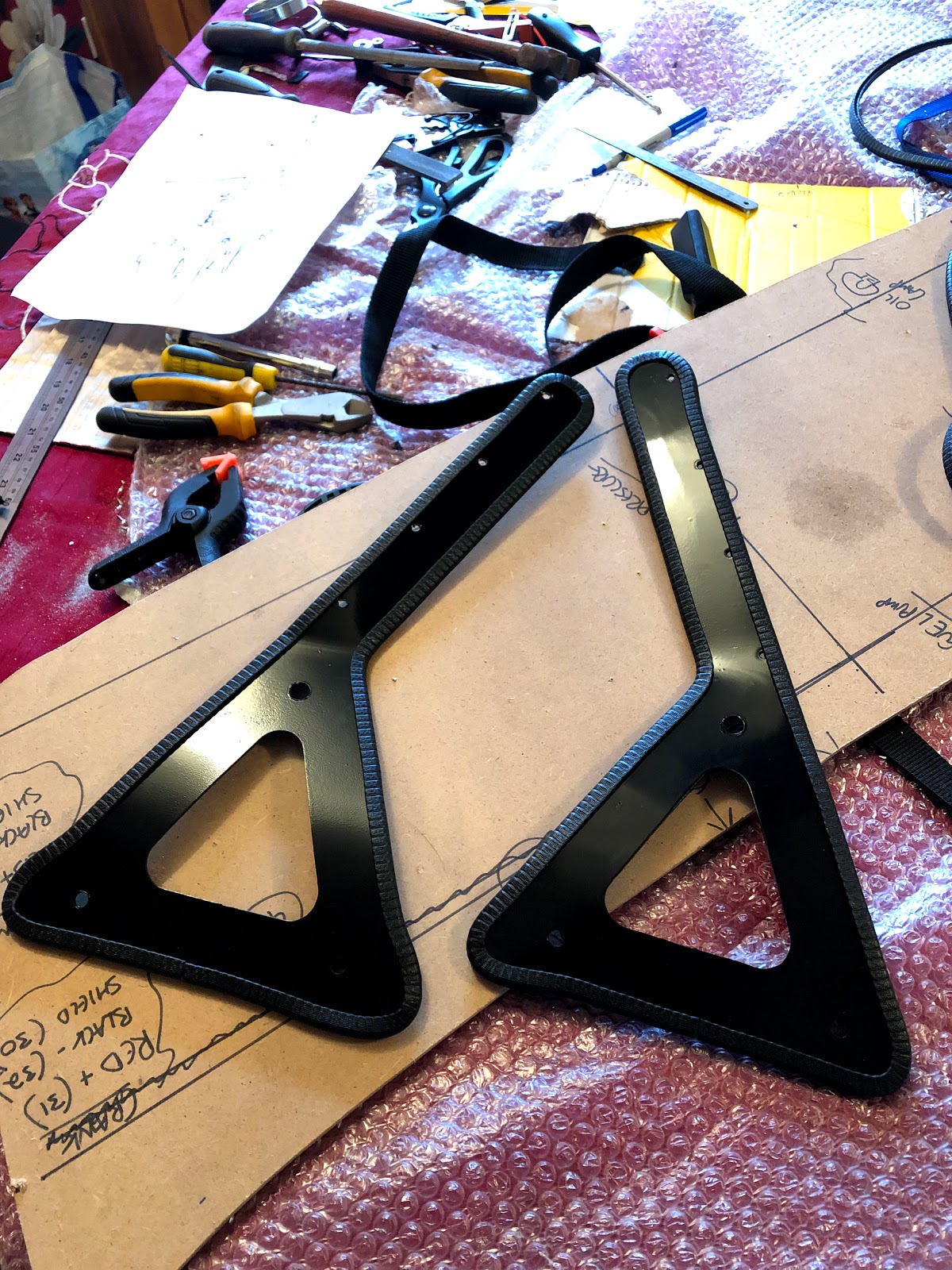
When both sides were completed I started the paint prep work and began several coats of hamerrite spray paint - it gives a good, long lasting finish:

After several days drying in the heat I fitted the trim - this is a requirement for the IVA.  I actually like the look of it as well:


Really chuffed with the finish I managed to achieve.  Next update will be the windscreen frame and fitment.

Windscreen Part 1

Time to fit the windscreen - what a marathon this became.  It seems I am so close to finishing yet every "little job" ends up taking forever to complete, no exception here.

The windscreen surround is roughly the right shape but isn't close enough to tighten into place:


I had driven down to the factory to pick up the glass and with such a delicate item I decided to make a template out of some scrap board in the garage.  After some bending I managed to get the correct shape:


The corners need to be fastened together with a No4 screw cut to length, there really isn't a big enough target to hit without risking screwing into the glass without adding some material.  I took an offcut of the frame and drilled it out:


Once both sides were ready I cut the bottom frame to length, here is the result - pretty good:


It turns out cutting to length wasn't the best idea, I hadn't taken into account the rubber strip required when fitting the glass meaning the ends were too short.  You will see later on how I fixed this.

The actual mounting brackets needed to be bent to shape - lots of heating in the oven and some creative vice work later I had a decent fit:


Note the center lines used to make sure everything is central and lined up.  Not many pictures for hours of effort and fiddling to get to this stage.

Monday, 28 January 2019

Heater Matrix

Although I haven't blogged in a while I've been tinkering away.  I started to research the requirements for the windscreen and it quickly became obvious most people don't put a windscreen on until after the IVA.  I am not like most normal people :)

The reason people decide against the windscreen is it has to have the correct markings on it and also the stock mounting pillars from GBS are not IVA compliant because of their sharp edges.  The final requirement for IVA is also demisters, which is where this post comes in.

There are a couple of places that supply electronic demisters but reading reviews and the forum they are supposed to be naff, plus if I fix a heater than at least I may be able to keep my hands warm(ish!).

After lots of research I managed to find a small heater from car builder solutions which will fit nicely under the scuttle.  This whole process would be impossible to do had I not made the scuttle removable, so first task - remove scuttle:


Back in the warmth of the dining room - its getting cold out!  Whilst the scuttle is off I need to run a inlet\outlet for the matrix, my plan is to tap into the two silicon hoses, one on the edge of the thermostat housing and the other next to to water pump.   I bought some self cutting "tees" which worked perfectly after a quick trip out into garage:


Back into the warmth again, time for a brew and some thinking.  I started planning where to put everything underneath.  There really isn't much room and I decided to move the ECU from its current location to the right hand side (moved again later on!).  Original location:


New location as you can see, the matrix now sits where the ECU once was:


I will explain how I fitted the grey tube in the middle which goes to the air vents in an upcoming blog.

Sunday, 9 September 2018

Engine - First Start :D

Well its taken me two days to finally get the engine started!  No major dramas all just fiddly stuff and I have a list of things that need sorting - the main thing is she started and she sound sweet :)

I have lost count of the number of times I checked the pinouts for the ECU and it turns out all the hard work payed off (with one minor adjustment I'll explain later).

I'd done all of my pre flight checks, the warning lights on the dash have been completed and the ECU turns on:


After a trip to the garage for some fuel it was time to turn the key and see if she starts.  Very nerve wracking, will it work or will there be a puff of smoke?  After checking my fire extinguisher was in reaching distance and wheeling the car out of the garage I turned the key to position 2 - fuel pump whirred into action, turning one more time the car tried to start.  Great - at least the starter motor works!  And.....nothing....not even a splutter.  Tried a couple more times and gave up, something was wrong.

Turns out the first check I did was the right one - do we have fuel at the rail?  Nope.  The high pressure pump was fine, but, nothing coming though.  Checked the low pressure pump and....dead!  I had the earth cable the wrong way round (!!!).  Fixed...but still nothing.

After a few hours and RTFM it turns out the ECU will display a red light on power and a green light on crank - I only had a red light, no change during crank.  The engine RPM was also 0, meaning the crank position sensor wasn't giving the ECU a reading.  Time to go to bed and have a think.

Day two came and I did further reading and took the decision to cut off my nice and neat 2 pin junior connector and replace them with some spades, this allowed me to switch the pins round.

Great.  I went to give her another go and caught a hint of petrol, after checking it seems like the high pressure fuel pump was leaking!  After literally two hours of messing around eventually I took the whole thing out and wrapped some PTFE tape around the inlet - apparently I had missed it!   Leak sealed, petrol mopped up.....turned the key and...success!

There was a small leak coming from the temperature sensor so knocked the ignition off and....nothing....car didn't switch off!?!  After a mild panic I remembered I had decided not to tighten the battery terminals as pulled the negative lead off - that was the right decision.

Another couple of hours of head scratching and reading the Emerald manual I decided to connect both pins 11 and pins 28 together.  The ECU has pin number 11 attached to the ignition switch, giving a 12v switch supply, but it also receives power from the main relay (which powers the injectors, IACV etc).  It effectively has two supplies and it should sense when pin 11 loses power ("key off") and turn itself off - it didn't, that's one way of providing power to the ECU.  The other is to connect both 28 and 11 together to the switched supply - bingo!  Car now starts and stops :)

List of things to do:


  • Inspect low pressure fuel pump - it is weeping fuel, I suspect its the same issue as the high pressure pump.  PTFE is safe to use with fuel so I will re-fit with some on
  • Check fog light wiring - it blew a fuse when turned on
  • Check alternator wiring and charge - I don't think it is charging the battery, earth looks good but voltage at battery seems low (from memory it should be ~14v when engine running, but that could be wrong)
  • Adjust clutch - it will not engage, cable is lose.
  • Adjust wiring documentation to reflect pin changes
  • And more....


Sunday, 2 September 2018

Dashboard - Clocks and Wiring

Another productive weekend!  Lots and lots of fiddly bits to this, in the end I decided to use my new hole cutters - turns out that was the right decision.

Back in the house I spent a lot of time measuring the layout for the dash whilst watching Car SOS - living the dream!


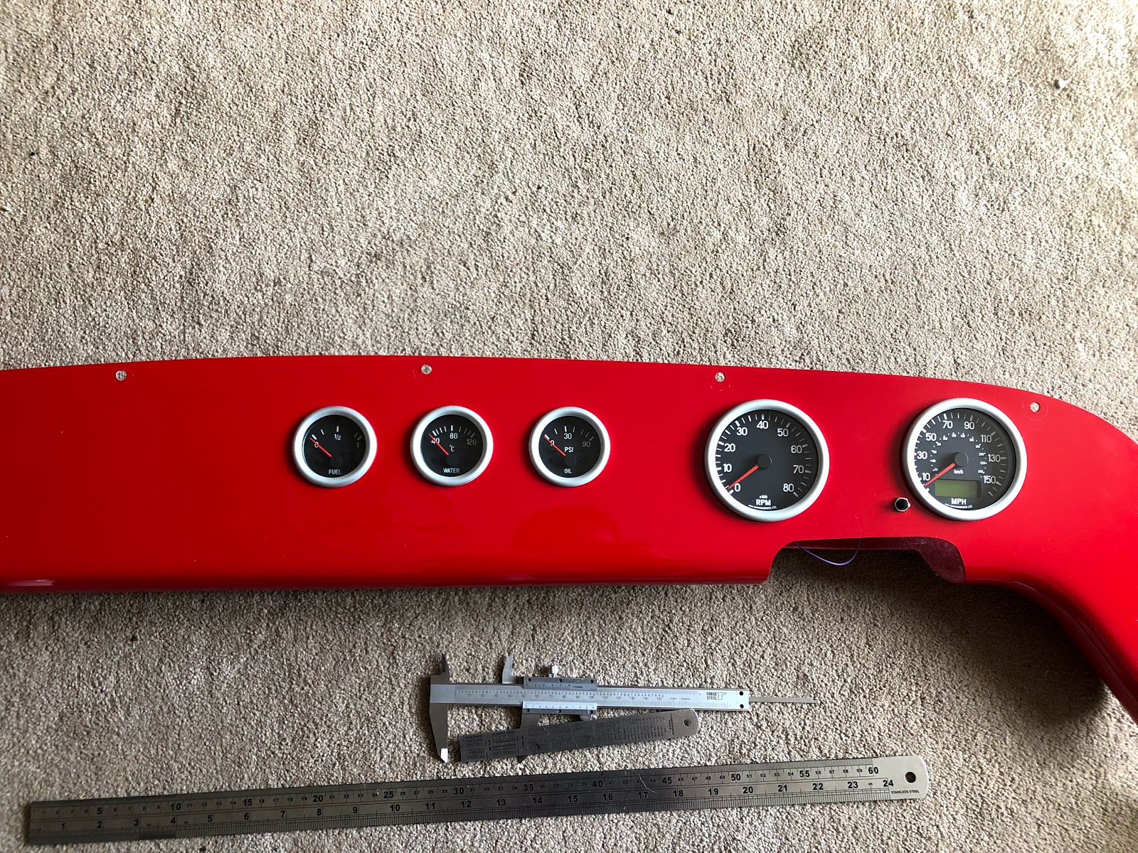
I went with ETB gauges which seem really good quality, the only problem was they dont come with any kind of template so it was either find a compass (and trust I get the circle right) or scout round the house finding some 80mm and 52mm circles.  I went for the latter :)  The tacco and speedo were done with a cup found in the kitchen.....the others took some hunting.  Finally I found what I was looking for:


Ready for cutting:


Note how each of the left hand dials drifted slightly off the line - they are actually equidistant.  Next few pictures show the process, drill using undersized cutter and then finish with the dremmel at low speed with sanding attachment:


Onto the wiring.  The documentation with the clocks is brilliant so it was easy to work out which wire goes where, coupled with the info I had gleamed from the forums for the dash fly-lead and my trusty multi-meter everything was a breeze.

Even though all this will be hidden I am positive its an IVA requirement to have the wires neatly tucked away plus its asking for problems just shoving them behind the dash, so I decided to cut a hole out the rear of the dash and fit a grommet:


Added a little braid and heat shrink:


There is method in the madness....

Almost finished:


The remaining wires are for the warning lights.  I am assuming the lights will need earthing and I'll probably spur them off one of the clocks, once the warning lights are in I can fit the dash for real.

I've been doing a lot of electrical testing on the car whilst I wait for the ECU and so far so good - as a result I couldn't resist seeing if all is OK with the dash!  The oil pressure sender isn't connected and I need to swap out the smiths fuel sender, everything else looks good and I have power and lights.


Wednesday, 29 August 2018

Tunnel Top Panels

Another easy job completed.  The top tunnel panels require holes drilling for the M6 dome heads and of course the hole for the gearstick needs to be carefully measured and then cut:


Everything fits nicely together.  Next job was to remove the protective plastic and give them a quick clean:


Same process as before applied, carpet glue and some patience:


Finished result, nothing is attached its all just resting in place until I complete the wiring, pilot holes and carpets:


Clocks will be here tomorrow so I suspect I will be wiring them in this weekend.

Tuesday, 28 August 2018

Aux Console

Nice and therapeutic one to do whilst waiting for the ECU and Clocks, gives me time to rest my back as well as 90% of this was done indoors.

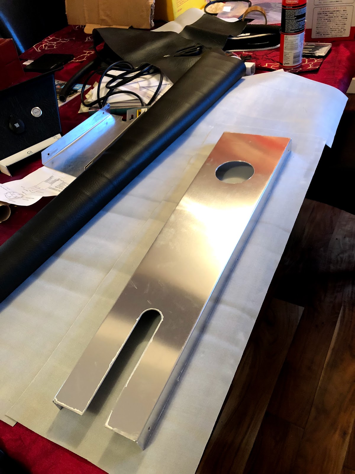
I purchased the lower dash panel from GBS, its made out of aluminium and it saves me having to fabricate something myself.  First job was to mark up the centre line and where I wanted each button to go:


A quick test of my hole driller on some scrap confirmed the fit and finish:


Onto the real thing....gulp.....and fhew, all fine without any drama:


Using the same leatherette I used for the dashboard I used some carpet glue and stuck it on - after much faffing about I am really pleased with the finish:


Out comes the scalpel:


And the final product:


Chuffed with that!  Hopefully that is the fiddliest part of the tunnel cover, I need to remember to cut out the leather for the pre-drilled holes ready for the dome head bolts.