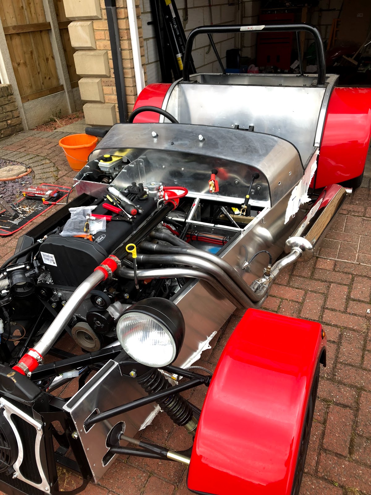
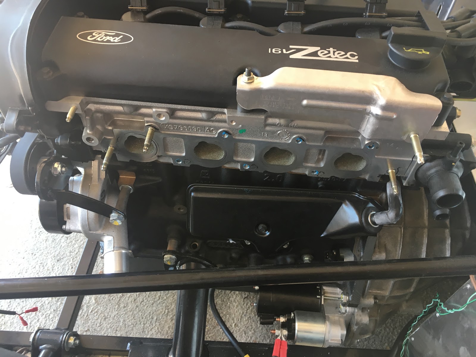
Lots done this bank holiday - getting closer to first start, the ECU and Clocks are on order and hopefully arrive before the weekend.
First job of the day was to set my stall up, took the car out of the garage as I knew the manifold would require some careful measuring and cutting:
Next job was to mark where the manifold needs to be cut based on the rear mount, I had some scrap aluminium in the garage which I used against the side of the car just in case:
Excess removed with my dremmel and the extension, great piece of kit. Next was onto the rear exhaust mount which needs to be drilled from underneath. I was planning on making up a template and then drilling through from the top, however as I only get one shot at it I put the rear on axle stands:
Then went for a pilot hole using my right angle adaptor
The manifold needs a bit of lube as its a tight fit, it must be done before final fitment of the rear bracket. Nice and neat:
Looking good:
Next onto the lambda sensor. I read on a couple of blogs that this needs to be kept connected to the sensor at all times due to the sensitivity of the device; I haven't confirmed this although chose to go with it. First task was to mark a pilot hole in the side:
The lamda sensor is the same size as a washer so I used that as template, masked it up and then opened up the hole with a mix of drill bits and eventually the dremel, nice and neat:
The three rivet holes allowed me to attach a clam shell which finishes off the hole nicely:
Looking good:
There were a handful of other jobs completed this weekend that dont really warrant pictures, one of which was the driveshaft - this must be split into two as it simply doesn't fit into the tunnel without.
I didn't have to remove either the gearbox or the diff to get it in and that's another thing ticked off.
I think I'll do some work on the centre console and aux switches as these can be done indoors before my ECU and Clocks arrive. Getting excited now :)
Monday, 27 August 2018
Sunday, 19 August 2018
IACV Mounting, Quick Shift and Exhaust Manifold
Lots of work completed that doesn't really photo well - the engine loom is fitted and well, you cant see it! (which is the general idea).
I spoke to GBS about mounting the IACV and they didn't say there was a specific place for it and recommended somewhere near the swirl pot. No room there so I posed on Rhocar to check my thoughts on mounting towards the front of the car near the radiator. I was concerned at the distance increase, no real consensus. I found on another builders blog they had mounted the IACV on the same bracket the coil pack sits on - that is what I went with and am really pleased with the result:
It looks almost stock! Great, filter required on the underside on one of the inlets and a vaccum pipe required other side going to the plenum - the end result should be nice and neat as well as functional.
Next up was the Exhaust Manifold - the manifold purchased from GBS must have a slightly thinner flange on it as the bolts don't nip up tight, they are about 2mm too long and as a result there is no way the manifold will seal. I did a fair amount of research on what type of bolts to use (with a couple of reference to GBS supplied ones) I came to the conclusion shortening the stock bolts was the way forward.
Using my vernier, dremmel and some patience all 6 bolts were cut to length and the manifold is now on:
Next up was the MT75 quick shift from Kitspares, the instructions are clear and it was easy to fit. I had to take off the existing "spider??" which was attached via circlip and pin, the left hand is the GBS replacement:
One thing I found easier was to keep the pin to temporarily connect the quick shift up to get the required 90 degree angle when in neutral.
GBS instructions say to finger tight everything up and then adjust the angle but the problem is to adjust the angle you have to take the bracket off. To find what the angle will be the selector needs to be connected to the gearbox, hence using the pin to temporarily connect.
Not too much of a faff and it feels really solid and well engineered:
I need to return the exhaust silencer I purchased from kitspares and swap it for one including CAT (I ordered the wrong one). I don't think I am too far off starting the engine but some big purchases are in order (clocks + ECU).
Sunday, 5 August 2018
Engine Loom - Part 2
Well, I hope it works :) I've spent so long on this loom but loved every minute of it. I didn't do it to save time or money, I did it to learn and I've definitely done that!
There aren't many pictures to this one as they don't really do it justice - in the flesh it looks good and I am confident all the pin outs are correct. I've tested every single one of them (several times!) and its now fitted to the car. The thing is its completely hidden away now, which is great and I have achieved what I wanted, the bad thing is no one will ever know the effort that went into it!
Some notes:
There aren't many pictures to this one as they don't really do it justice - in the flesh it looks good and I am confident all the pin outs are correct. I've tested every single one of them (several times!) and its now fitted to the car. The thing is its completely hidden away now, which is great and I have achieved what I wanted, the bad thing is no one will ever know the effort that went into it!
Some notes:
- Those of you with a keen eye will notice the Spartan2 wide band lamda controller on the left. After researching wide band, narrow band, closed and open loop systems I went with this (https://www.14point7.com/products/spartan-lambda-controller-2). Its a no brainer really, it make sense to go wide band and this is the best value\rated kit available.
- I'll cut the earth wire down to length and terminate it when the ECU is fitted, the earth point is already in place so required length is unknown.
- I'm waiting on a connector for the oil pressure switch, it was difficult to find but managed to find one available on eBay, should be here next week.
- The other connector I need is for the oil pressure clocks - that will come with the clocks when I purchase them. Still undecided if I should go down the smiths gauge route or go digital (digital is appealing most)
- Every single connection has been soldered, heat shrunk and tested - I took my time with each of them and made sure they were all 100%.
- Every pin has been tested for continuity, the wire gauge was defined by emerald in their fly lead.
- I used a combination of resources to map the various ECU pin outs and GBS engine loom pinouts. GBS were helpful on their forum when I asked for a pin out list for the engine harness, what I had already researched matched what I was told which is always a good sign
- The emerald documentation is great with detailed information including examples
- All of the connectors and sensors are available direct from emerald
- The Ford wiring diagram I have was very helpful, especially working out sensor pins
Its now in the car, done. Its been a mission and I am now one step closer to turning they key....
Pinouts are as below - please feel free to use these for reference but of course do *not* take them as gospel, check your own and do your own reasearch!
Emerald K6 Pins
| PIN | CONNECTION | COMMENTS |
| 1 | Injector Driver 2 | Injector Driver 2, PIN 2 as per manual |
| 2 | N/A | N/A |
| 3 | IACV PWM control output | IACV PWM control output, PIN 2 |
| 4 | Main Relay Driver | To ENGINE HARNESS PIN 3, Pink |
| 5 | COIL 2 (CYL 2+3) | To coil pack PIN 3 (Cylinter 2 +3) |
| 6 | Cooling fan relay control | To ENGINE HARNESS PIN 4, Orange |
| 7 | N/A | N/A |
| 8 | TPS Input | To TPS Input PIN 2 |
| 9 | Lambda Supply | Lambda Supply - SPARTAN2 (TBC) |
| 10 | N/A | N/A |
| 11 | Ignition sense input | 12v supply via ignition switch, to ENGINE HARNESS PIN 1, Red. Also IACV PIN 1 |
| 12 | Tacho output signal | 0-12v pulsed output, to ENGINE HARNESS PIN 6, Purple |
| 13 | N/A | N/A |
| 14 | N/A | N/A |
| 15 | Cam Position Sensor Input | To Cam Sensor, PIN 1 |
| 16 | Air temperature signal input | Air temperature sensor input |
| 17 | N/A | N/A |
| 18 | N/A | N/A |
| 19 | Shift-light driver | Shift-light output (switched earth), to ENGINE HARNESS PIN 7, Grey |
| 20 | Fuel pump relay driver | Fuel pump relay driver, to ENGINE HARNESS PIN 5, Green |
| 21 | N/A | N/A |
| 22 | N/A | N/A |
| 23 | Injector driver 3 | Injector Driver 3, PIN 2 as per manual |
| 24 | Injector driver 1 | Injector Driver 1, PIN 2 as per manual |
| 25 | COIL 1 (CYL 1+ 4) | To coil pack PIN 1 (Cylinter 2 +3) |
| 26 | Injector driver 4 | Injector Driver 4, PIN 2 as per manual |
| 27 | N/A | N/A |
| 28 | +12v Ignition supply | Supply from main relay or common with pin 11, to ENGINE HARNESS PIN 2, Black. Also to coli pack PIN 2 and ALL INECTORS @ PIN 1 |
| 29 | ECU earth | Good earth (direct to battery), also to HP Fuel Pump. |
| 30 | Sensor earth | Common earth for air, coolant & throttle sensors. To Crank Shield, TPS PIN 1, Coolant ECU Sensor, Air ECU Sensor, Lambda Driver SPARTAN |
| 31 | Crank, main trigger signal input | Crank sensor, PIN 1 |
| 32 | Main trigger sensor earth | Earth return for main/cam trigger sensors. To Crank sensor, PIN 2 and CAM sensor, PIN 2 |
| 33 | Coolant temp signal input | To coolant ECU sensor |
| 34 | Lambda Power | Lambda input SPARTAN |
| 35 | AuxIn35 | Removed - however, cable left in loom and terminated. |
| 36 | N/A | N/A |
GBS Engine Loom Pins
| PIN # | COLOR | COMPONENT | TO ECU | EMERALD PIN |
| 1 | RED | 12v ignition supply (switch) | YES | 11 |
| 2 | BLACK | ECU ignition relay supply | YES | 28 |
| 3 | PINK | main relay control (coil, Injection, Lambda) emerald switches this to earth | YES | 4 |
| 4 | ORANGE | cooling fan relay drive, emerald switches this to earth | YES | 6 |
| 5 | GREEN | fuel pump relay driver, emerald switches this to earth | YES | 20 |
| 6 | PURPLE | tachometer output signal | YES | 12 |
| 7 | GREY | shift light driver | YES | 19 |
| 8 | WHITE | oil pressure gauge | NO | N/A |
| 9 | YELLOW | oil pressure warning lamp | NO | N/A |
| 10 | PURPLE | water temp gauge | NO | N/A |
| 11 | RED | alternator warning lamp red horizontal terminal on alternator | NO | N/A |
| 12 | GREY | fuel pump + grey supply for high pressure fuel pump | NO | N/A |
Tuesday, 10 July 2018
Plenum
I purchased the GBS Plenum, it replaces the stock intake manifold and its a great piece of kit. It also seems like a have version 2.0 - the addition of a hose connector. This one baffled me for a while but it looks like I have two options.
Option 1 - bung the hole and adjust the throttle screw to get the idle correct. This is what I had originally intended on doing, admittedly because I didn't understand what an IACV was.
Option 2 - connect up a remote IACV. Now that I know what it does (and that GBS sell a mounting bracket) I am going to chose this option. The Emerald ECU has instructions on how to setup the IACV when its required and I am looking forward to that challenge; if I can't do it I will be able to find someone who can.
The Plenum is very well made and comes powder coated. The original manifold needs to be cut down and this is a service that GBS do and I would recommend it as it needs to be done correctly:
There is also a threaded hole which accepts the air temperature sensor - top tip from me (common sense now...) clean the thread out *before* fitting the Plenum to the car!
I wasted around an hour of absolute faffing around trying to fit the sensor and it was impossible whilst on the car. I actually ended up cleaning the thread out after checking the sensor size and thread pitch on the emerald site (M12 1.5 BTW):
Once the thread was cleaned up the sensor went in fine, throttle body attached to the car and we are done:
The fuel rail will be sorted later on, its simply resting to seal the holes up. Looking very much like an engine now:
Option 1 - bung the hole and adjust the throttle screw to get the idle correct. This is what I had originally intended on doing, admittedly because I didn't understand what an IACV was.
Option 2 - connect up a remote IACV. Now that I know what it does (and that GBS sell a mounting bracket) I am going to chose this option. The Emerald ECU has instructions on how to setup the IACV when its required and I am looking forward to that challenge; if I can't do it I will be able to find someone who can.
The Plenum is very well made and comes powder coated. The original manifold needs to be cut down and this is a service that GBS do and I would recommend it as it needs to be done correctly:
There is also a threaded hole which accepts the air temperature sensor - top tip from me (common sense now...) clean the thread out *before* fitting the Plenum to the car!
I wasted around an hour of absolute faffing around trying to fit the sensor and it was impossible whilst on the car. I actually ended up cleaning the thread out after checking the sensor size and thread pitch on the emerald site (M12 1.5 BTW):
Once the thread was cleaned up the sensor went in fine, throttle body attached to the car and we are done:
The fuel rail will be sorted later on, its simply resting to seal the holes up. Looking very much like an engine now:
Alternator
I enjoyed this one. I had already been given an alternator for free when I purchased my flywheel, unfortunately the brackets didn't fit so I thought I would save the time and effort required and went for the GBS kit. Everything required to fit the alternator is in the kit:
The brackets are all power coated and its obvious they are very good quality - one of the good things I like about the GBS supplied parts. The bad thing is they came with no instructions only a note saying download them off the kitspares site; the problem with that is they are a set of pictures. From what I could see the pictures were also of two different types of alternator and brackets (I think!).
It felt a little bit like when you buy Ikea furniture, at first it makes no sense at all but when you are half way though it all comes together. Anyway if you do buy the kit you will have no problems fitting it and working out how it fits together, for me it was a nice and easy couple of hours work:
You can see I removed one of the metal "bolts" in the block, both need to be removed and are not required.
The tensioner pulley is attached as per the picture. I had to take it off at first go as I mounted it in the hole above the manifold (I wasn't paying attention...). It also connects to the front of the block and is very sturdy:
Next we have to remove the lifting eye and fit the bracket which is attached to the rear of the alternator top hole:
There are a number of washers required to make sure the alternator is square, I used a piece of wood at the front to check.
The bottom bracket connects to the engine block and again a few washers are required to pad out the bottom bolt. Time to fit the belt:
The tension looks OK but I need to check how to tension it up correctly - I guess I will find out later on!
The brackets are all power coated and its obvious they are very good quality - one of the good things I like about the GBS supplied parts. The bad thing is they came with no instructions only a note saying download them off the kitspares site; the problem with that is they are a set of pictures. From what I could see the pictures were also of two different types of alternator and brackets (I think!).
It felt a little bit like when you buy Ikea furniture, at first it makes no sense at all but when you are half way though it all comes together. Anyway if you do buy the kit you will have no problems fitting it and working out how it fits together, for me it was a nice and easy couple of hours work:
You can see I removed one of the metal "bolts" in the block, both need to be removed and are not required.
The tensioner pulley is attached as per the picture. I had to take it off at first go as I mounted it in the hole above the manifold (I wasn't paying attention...). It also connects to the front of the block and is very sturdy:
Next we have to remove the lifting eye and fit the bracket which is attached to the rear of the alternator top hole:
There are a number of washers required to make sure the alternator is square, I used a piece of wood at the front to check.
The bottom bracket connects to the engine block and again a few washers are required to pad out the bottom bolt. Time to fit the belt:
And complete:
The tension looks OK but I need to check how to tension it up correctly - I guess I will find out later on!
Cooling System
Over a year has gone by - I have been busy, unfortunately the car has had to take a back seat but here I am, back on it and jumping straight back in at the deep end.
So, onto the Cooling System! I placed an order with GBS last week and purchased everything necessary for to complete the cooling side of the engine. The kit is really good quality and comes with everything you need, there aren't any instructions but its fairly self explanatory - previous blog posts helped.
The kit as it came:
You will notice the mounting bracket that connects to the steering column mounts, the tube is pretty solid in place but I guess after a while and with a lot of heat cycles the hoses will get softer and maybe sag. Its a GBS part and easy to fit, the pipe itself is attached to the bracket via cable tie.
So, onto the Cooling System! I placed an order with GBS last week and purchased everything necessary for to complete the cooling side of the engine. The kit is really good quality and comes with everything you need, there aren't any instructions but its fairly self explanatory - previous blog posts helped.
The kit as it came:
The water rail kit gives you all you need to setup the rail only, you do need to purchase the additional pipes to route from the water pump and the rail to the radiator. I forgot to photo the contents of the kit however you will see it later on as I progressed.
First step was to remove the stock Exhaust Manifold, then the oil flame trap - there's a bit of discussion as to whether this is required - however the norm is to remove and block it off, which I have decided to do with the ATR blanking plate from GBS:
Much better and more room. Next was removing the stock thermostat housing, cleaning and replacing with the GBS part (much more sturdy!). Based on my previous experience with coolant systems a small smear of gasket seal was in order too...
I've also fitted the dipstick - straight forward. Next it was time to fit the radiator and fan, really simple and a 10 minute job although a quick read of other blogs helped (tabs need to be bend backwards so the radiator sits on the inside of the mount otherwise nose cone will not fit):
Looking good! Onto plumbing her in....again, another simple job that requires a methodical approach:
You will notice the mounting bracket that connects to the steering column mounts, the tube is pretty solid in place but I guess after a while and with a lot of heat cycles the hoses will get softer and maybe sag. Its a GBS part and easy to fit, the pipe itself is attached to the bracket via cable tie.
Saturday, 12 August 2017
Engine Fitted
Time is marching on and progress is slow on the Car. Its been a tough few months, I've started my own business which is fun but at the same time stressful and funds are still tight. The car has had to take a back seat. I'm still itching to make progress but its difficult to find the time and frankly motivation with everything else going on, but, I do have an update.
The engine has been fitted, I purchased a lowered sump and fitted it and I also re-made the gearbox mount - I wasn't happy enough with the previous one.
Old sump removed, don't forget to remove the bold holding the pickup on. Also I missed a bolt right next to the flywheel, frustratingly I spent ages trying to split the oil pan from the aluminum. I thought it was just suction but alas a pesky bolt was still on.
Old sump removed and ready for the scrap man. Seems a shame to throw it out but its no use to me and goes for pennies on eBay.
New sump ready to be fitted, I used some gasket seal - based on the research I have done, it should be absolutely fine for the job.
Sump fitted:
The starter motor is missing from the pic but it's also now fitted.
And engine in:
I need to buy a modified inlet manifold from GBS as the stock on doesn't fit, plus a plenum. That's it for now. Garage cleanup due.
The engine has been fitted, I purchased a lowered sump and fitted it and I also re-made the gearbox mount - I wasn't happy enough with the previous one.
Old sump removed, don't forget to remove the bold holding the pickup on. Also I missed a bolt right next to the flywheel, frustratingly I spent ages trying to split the oil pan from the aluminum. I thought it was just suction but alas a pesky bolt was still on.
Old sump removed and ready for the scrap man. Seems a shame to throw it out but its no use to me and goes for pennies on eBay.
New sump ready to be fitted, I used some gasket seal - based on the research I have done, it should be absolutely fine for the job.
Sump fitted:
The starter motor is missing from the pic but it's also now fitted.
And engine in:
I need to buy a modified inlet manifold from GBS as the stock on doesn't fit, plus a plenum. That's it for now. Garage cleanup due.
Subscribe to:
Posts (Atom)